Homebrew, open source, repurposed, hacked, software defined, open hardware

Sunday 16 April 2017

Bitmap import now supported by pcb-rnd, including Easter eggs


Support for parametric footprints within pcb-rnd, the gEDA PCB fork, now allows on the fly insertion of any graphic file type as a silkscreen bitmap, including easter egg depictions, of course, that are supported by the netpbm package that the bitmap() script depends on.

At this point in time, netpbm supports:

bmp, fiasco, fits, gem, gif, jpeg, palm, ps, rast, rle, sgi, sir, tiff, xwd, zeiss, png

which means that any of these image formats can be inserted, on the fly, into a pcb-rnd PCB layout as a bitmap.

The bitmap() script can be found on the edakrill repository.

The script files need to be installed in the search path for parametric footprint elements, i.e.

    pcb-rnd/trunk/pcblib/parametric/

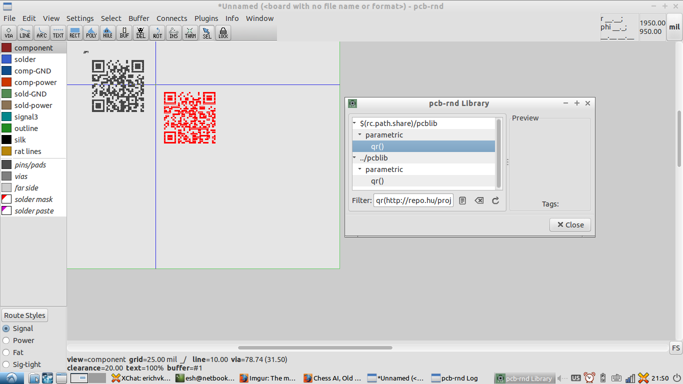
The footprint insertion dialogue is invoked with the usual "i" command, at which point the path to the image can be entered into the bitmap() footprint dialogue as follows, along with pixel size details:


At which point the graphic is turned into an element in the buffer:


Which can then be placed on the layout:


This is a somewhat simpler way of inserting images than other workflows including the use of pstoedit or image2footprint, previously described, which are used standalone to generate the layout element for subsequent insertion into the PCB layout.

Image size and resolution should be kept sensible, as the resulting footprint silkscreen elements will get quite big and bloat a layout if excessively high resolution images are used, and may encounter manufacturer limitations with minimum silkscreen dimensions, i.e. less than 6 or 8 mil, depending on the manufacturer.

Sunday 9 April 2017

Line, Polygon and Arc objects now supported in pcb-rnd font glyphs

Further work on multiple font support in pcb-rnd  handling has  led to the addition of support for not just polygons within glyphs, but also arc objects. Until now, gEDA PCB and pcb-rnd have been limited to line objects only within glyphs.

pcb-rnd's   :FontEdit   code has been updated to allow arcs to be edited and saved by those wishing to create their own fonts or modify existing fonts. Those familiar with   :FontEdit   and   :FontSave   will appreciate the ability to use arcs when creating rounded glyphs in a new font:


Fonts with arc objects can be saved as standalone font files in pcb-rnd's new lihata (.lht) file format. These font files can then be easily shared, and loaded into a pcb-rnd layout with the font load window (CTRL-SHIFT-F).

Here is an example of an arc based default font, (default_arc.lht) alternative to the legacy default_font:


Multiple fonts can be used simultaneously in pcb-rnd; here is the traditional default_font shown above the arc based example font:


Advantages of the new arc-based font are more compact gerber export, and more compact font description files, since three or more lines can be replaced with just one arc description.

The traditional default_font remains the default font in pcb-rnd, but users are free to try out the example arc based font in the trunk/font directory in addition to the traditional default_font in the trunk/src directory if keen.

The default_arc.lht example arc based font is a working example of the new font file syntax, and can be referred to by those keen to design their own fonts.

Those crafting new font files in lihata (.lht) format should find the format quite human parseable, and need only note that hashes of the form

  ha:j {

  }

which contain details for a particular glyph, in this case, "j", need have the character escaped if the hash refers to one of the following ASCII chars:

  {     }      \      :      ~     ;     =     &     #

and also ASCII 32, the space character, for lihata parsing to behave properly.

Examples of how to do this can be seen in the default_arc.lht example file, either by pulling down an svn copy of the repo, or browsing the repo online at

http://igor2.repo.hu/cgi-bin/minisvn.cgi?cmd=browse&repo=pcb-rnd&path=trunk

pcb-rnd also supports multiple font editing options with the updated   :FontEdit   code via the miantenance menu, allowing editing of the current font within a layouts, or editing of fonts residing on disk:


Thursday 6 April 2017

QR code and code128 barcode support for PCB layouts now in pcb-rnd, the gEDA PCB fork

As part of the extensible parametric footprint support in the gEDA PCB fork, pcb-rnd, support for QR-codes and code128 barcodes on pcb layouts has been implemented.

The necessary awk scripts can be obtained from the EDAkrill repository, http://repo.hu/projects/edakrill/

Installation of the qrencode library on the machine running pcb-rnd is required.

A QR-code can be instantiated with a footprint attribute like:

 qr(hello world, 37.00mil)

or

 code128(hello world, 0.001m)

embedded in a netlist exported from a schematic. The dimension refers to the pixel size.

Of note, parametric footprints scripts are able to parse the usual dimension suffixes, i.e. mm, mil, dmil, cmil, in, um

Alternatively, and somewhat simpler, is to simply use the "i" element insertion dialogue within the layout editor to provide the text and pixel dimensions for insertion as a QR-code, i.e.


The QR-code text and pixel size can be selected, along with either high or low level error coding:


After this, the QR-code can be placed on the layout, like any footprint element:


and here's the QR-code with a bit of zoom applied...


Similarly, a code128 format barcode can be instantiated with a footprint attribute like:

  code128(hello world, 1000.00um)

or

  code128(hello world, 0.1cm)

or by instantiating the "i" insert element dialogue, i.e.


after the height, barcode bar width and text are defined, the element can be placed on the layout:


Like any footprint element, the text label can be resized and moved.


A footprint created this way can be saved from the buffer either before placement, or after copying into the buffer, if a standalone footprint is required, i.e. for importing into KiCad or frequent use.

Of note, the pairs of awk scripts that implement the qr() and code128() parametric footprints need to be placed in pcb-rnd's

   trunk/pcblib/parametric

directory, and can serve as templates for your own modifications or alternative parametric footprint types which will automatically show up in the element insertion dialogue on restarting pcb-rnd, if placed in this directory.

Over time, additional user contributed awk scripts for parametric footprints will also be available on edakrill, the new platform and  format agnostic EDA repository.