A 10.7MHz intermediate frequency transformer, also known as an IF can, is commonly used in the IF strip of FM radios.
A 10.7 MHz IF can, with minor modifications, seemed ideal for as a 10Mhz variable inductor for this particular purpose as its usual frequency of operation was close to the required frequency.
The "Xicon 42IF123" IF can was available from www.minikits.com.au and was selected.

The first step is to remove the small capacitor in the base of the can, visible from underneath. As shown in the circuit diagram, the capacitor is in parallel with the tapped primary coil of the transformer, and allows the primary to resonate at around 10.7MHz. It is not needed if the IF can is to be used simply as an inductor.

The capacitor can be removed with a sharp knife, scalpel, or similar.

The shielding can is then carefully removed from the plastic base, taking care not to damage the vertical ferrite bobbin with the windings.

The tapped winding between pins 1 and 2 was calculated to have an inductance range: 2.5uH - 4.5uH
The primary winding between pins 1 and 3 was calculated to have an inductance range: 5.5uH - 10uH
The secondary winding between pins 4 and 6 was calculated to have an inductance range: 0.269uH - 0.383 uH
To use the tapped primary winding between pins 1 and 2 in a standard G3UUR colpitts circuit oscillating at around 10MHz required the inductance to be reduced around 30-40%. Without modification, the winding between pins 1 and 2 allowed a standard G3UUR colpitts circuit to oscillate between around 6.0MHz and 8.0MHz
There appeared to be about eight turns for the winding between pin 1 and 2, which, conveniently, was the most accessible winding, located at the top of the ferrite bobbin.
Accordingly, to effect a reduction in inductance of about 30-40%, three turns had to be removed.
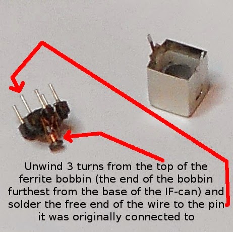
After three turns had been unwound, the wire was carefully scraped clean of enamel insulation and re-attached to pin 1 with the soldering iron, after which the shielding can was replaced. The windings were then checked for continuity with a multimeter.
After confirming continuity of the windings, the modified IF can was placed in the G3UUR colpitts circuit using the winding between pins 1 and 2 in place of the crystal.The oscillator could now be tuned from around 9.0MHz up to 11.0Mhz, which achieved the intended goal of 10MHz operation.