Homebrew, open source, repurposed, hacked, software defined, open hardware

Monday 13 October 2014

Citrix Access Gateway 2010 phoenix BIOS and lubuntu linux installation

Hmm, an unloved, discarded, Citrix Access Gateway. IEC power socket and a USB socket at the back, as well as two ethernet ports, and a DB9 serial port at the front. Are those mini DIN keyboard and mouse sockets hiding behind the front panel?
I wonder if we can repurpose this as a rack mounted linux box? 


 Inspection of the back panel confirms it is a Citrix Access Gateway (CAG) model 2010


Time to void the warranty...


It's got a super server motherboard, 80 GB HDD, P4 pentium processor, a PCI card riser and 2x512MB = 1GB RAM on board, and it seems we don't need to do a headless server installation of linux, since it has a VGA port and a few more USB ports available.


The server booted off a lubuntu 14.04 USB installer without complaint. Luckily the BIOS did not need to be told to boot off the USB stick ahead of the HDD.


The installation went smoothly, and sucked down the additional packages over ethernet. sshd was also installed to allow access over the local network.
 

The box didn't want to power down fully, or quieten the cooling fans, which were running at full speed. The BIOS was locked down with a password, so hitting Delete on booting wasn't helpful.

Attempts to short the JBT1 pads with the power disconnected and leaving the lithium cell CMOS battery out overnight did not get rid of the BIOS password.

The python script listed below for Phoenix BIOS password checksums was found and successfully used to brute force the Citrix Access Gateway BIOS password checksum [06626].

The BIOS password error checksum was: [06626]
The Citrix Access Gateway 2010 BIOS password was found to be: bfsyxxm

The Citrix Access Gateway 2010 model uses a generic pheonix BIOS checksum, it seems.

Entering the BIOS password allowed the BIOS password to be changed to something easier to remember, and the "always power on", and "full speed" fan settings were able to be changed, to make the unit quieter and able to power down properly.

Here's the python script used to brute force the BIOS password:
#!/usr/bin/python

# Copyright 2009:  dogbert <dogber1@gmail.com>
#
# This program is free software; you can redistribute it and/or modify
# it under the terms of the GNU General Public License as published by
# the Free Software Foundation; either version 2 of the License, or
# (at your option) any later version.
#
# This program is distributed in the hope that it will be useful,
# but WITHOUT ANY WARRANTY; without even the implied warranty of
# MERCHANTABILITY or FITNESS FOR A PARTICULAR PURPOSE.  See the
# GNU General Public License for more details.
#
# You should have received a copy of the GNU General Public License
# along with this program; if not, write to the Free Software
# Foundation, Inc., 59 Temple Place, Suite 330, Boston, MA  02111-1307  USA
#

# This script generates master passwords which can be used to unlock the BIOS
# password of most Phoenix BIOS versions. It also works for some versions of
# FSI, HP and Compaq laptops which use slightly different hashing algorithms
# in the BIOS.
# You have to install python 2.x for running this script.

import os, random

keyboardDict = {  2: '1',  3: '2',  4: '3',  5: '4',  6: '5',  7: '6',  8: '7',  9: '8', 10: '9', 11: '0',
                 16: 'q', 17: 'w', 18: 'e', 19: 'r', 20: 't', 21: 'y', 22: 'u', 23: 'i', 24: 'o', 25: 'p',
                 30: 'a', 31: 's', 32: 'd', 33: 'f', 34: 'g', 35: 'h', 36: 'j', 37: 'k', 38: 'l',
                 44: 'z', 45: 'x', 46: 'c', 47: 'v', 48: 'b', 49: 'n', 50: 'm' }

def keyboardEncToAscii(inKey):
    out = ""
    for c in inKey:
        if c != 0: out += keyboardDict[c]
    return out

def asciiToKeyboardenc(inAscii):
    out = []
    asciiDict = dict([(a,k) for k,a in keyboardDict.iteritems()])
    for c in inAscii:
        if c != 0: out.append(asciiDict[c])
    return out


# The phoenix implementation of the CRC-16 contains a rather severe bug
# quartering the image space of the function: both the first and second MSB
# are always zero regardless of the input.
# For a working implementation, you'd have to change the polynom from 0x2001
# to e.g. 0xA001.
def badCRC16(pwd, salt=0):
    hash = salt
    for c in pwd:
        hash ^= c
        for i in range(0,8):
            if (hash & 1):
                hash = (hash >> 1) ^ 0x2001
            else:
                hash = (hash >> 1)
    return hash


def bruteForce(hash, salt=0, digitsOnly=False, charsOnly=True, minLen=3, maxLen=8):
    global keyboardDict
    keyboardDictOrig = keyboardDict
    if digitsOnly:
        keyboardDict = dict(zip(list(keyboardDict.keys())[0:9],list(keyboardDict.values())[0:9]))
    elif charsOnly:
        keyboardDict = dict(zip(list(keyboardDict.keys())[10:36],list(keyboardDict.values())[10:36]))

    encodedPwd = []
    for i in range(0, 7):
        encodedPwd.append(list(keyboardDict.keys())[0])
    random.seed()
    if hash > 0x3FFF:
        return "invalid hash code"
    while 1:
        # generate random password
        rndVal = random.random()*len(keyboardDict)
        for i in range(0,len(encodedPwd)):
            value = int(rndVal % len(keyboardDict))
            encodedPwd[i] = list(keyboardDict.keys())[value]
            rndVal = rndVal * len(keyboardDict)
        # test substrings of the random password
        for i in range(minLen, maxLen+1):
            if badCRC16(encodedPwd[0:i], salt) == hash:
                keyboardDict = keyboardDictOrig
                encodedPwd = encodedPwd[0:i]
                return keyboardEncToAscii(encodedPwd[0:i])


print("Master Password Generator for Phoenix BIOS (five decimal digits version)")
print("Copyright (C) 2009 dogbert <dogber1@gmail.com>")
print("")
print("After entering the wrong password for the third time, you will receive a")
print("decimal number from which the master password can be calculated,")
print("e.g. 12345")
print("")
print("Please enter the number: ")
code = raw_input().replace('[', '').replace(']', '')
hash = int(code)
print("")
print("Brute forcing passwords...")
print("Generic Phoenix BIOS:          " + bruteForce(hash, 0))
print("HP/Compaq Phoenix BIOS:        " + bruteForce(hash, salt=17232))
print("FSI Phoenix BIOS (generic):    " + bruteForce(hash, salt=65, minLen=3, maxLen=7,digitsOnly=True))
print("FSI Phoenix BIOS ('L' model):  " + bruteForce(hash+1, salt=ord('L'), minLen=3, maxLen=7,digitsOnly=True))
print("FSI Phoenix BIOS ('P' model):  " + bruteForce(hash+1, salt=ord('P'), minLen=3, maxLen=7,digitsOnly=True))
print("FSI Phoenix BIOS ('S' model):  " + bruteForce(hash+1, salt=ord('S'), minLen=3, maxLen=7,digitsOnly=True))
print("FSI Phoenix BIOS ('X' model):  " + bruteForce(hash+1, salt=ord('X'), minLen=3, maxLen=7,digitsOnly=True))
print("")
print("done.")
print("")
print("Please note that the password has been encoded for the standard US")
print("keyboard layout (QWERTY).")
if (os.name == 'nt'):
    print("Press a key to exit...")
    raw_input()

Tuesday 23 September 2014

geda PCB font utilities and options including hebrew, greek, cyrillic and unicode CJK glyphs

I have converted some of the free Hershey fonts for use with the free and open source geda PCB design software, after starting with Hershey Sans 1 stroke to provide a more contoured default font.

In the process I wrote a small piece of C code pcbFontTool.c to simplify processing of pstoedit outputs and conversion into PCB Designer compatible font symbols.

Having streamlined the process somewhat, I figured why not do some of
the other fonts, so, PCB users now have the choice of:

Hershey Sans 1 stroke
Hershey German Gothic
Hershey Italian Gothic
Hershey English Gothic
Hershey Cyrillic - with keyboard mapping to be determined by user
Hershey Greek - with keyboard mapping to be determined by user

and the usual default_font

I have uploaded the fonts, the pcbFontTool utility, and instructions for those wishing to convert other fonts, to an ftp server

The license for pcbFontTool.c is GPL v2  or at the user's option GPL v3. The code could be improved but it does the job quite effectively.

These fonts are a simple drop in replacement for default_font, which at this stage lives in /geda/pcb/src
Until we have a mechanism for selecting fonts in PCB, this is what users will have to do.

I strongly recommend that anyone using geda PCB install git, clone the git repository, and build a local version of PCB so that they are running the latest version of PCB.

The pcbFontTool.c utility is standalone, only uses stdio, and has an attached README.txt

users.on.net/~esh/geda/pcb/src/fonts/README.txt

The gothic and sans fonts use the normal ASCII/US keyboard mapping.

The cyrillic font uses a keyboard mapping based on the Hershey fonts as distributed.
There are four or more types of cyrillic keyboard mapping in use, so a glyph table has been included to assist anyone trying to use it.

Likewise for the Greek font, a glyph table is included and PCB users will need to determine how they want to map the symbol to their keyboard. Users will have to add their own accents to the Greek vowels. There is a glyph table to show the Greek mapping as well.
 
The issue of CJK (Chinese, Japanese and Korean) glyphs was looked at next.

The GNU unifont bdf is available from unifoundry, which has released the GNU unifont as a free and open source font for use in FOSS.

http://unifoundry.com/pub/unifont-7.0.03/font-builds/unifont-7.0.03.bdf.gz

hosted by:

http://unifoundry.com/unifont.html

The reason that the GNU unifont has been made available in bdf format is because the bdf format is commonly used by X windows systems

http://en.wikipedia.org/wiki/Glyph_Bitmap_Distribution_Format

The bdf font file is a series of consecutive symbol definitions of the form:

STARTCHAR U+004E
ENCODING 78
SWIDTH 500 0
DWIDTH 8 0
BBX 8 16 0 -2
BITMAP
00
00
00
00
42
62
62
52
52
4A
4A
46
46
42
00
00
ENDCHAR

Chinese, Japanese and Korean (CJK) glyph rendering is not trivial and the approach taken by others has been to use bitmapped glyphs for resolutions below 16x16 pixels, and vector font formats for larger sizes.

The GNU unifont project has an essentially complete set of CJK glyphs in 11x11, 12x12, 13x13, 14x14, 15x15 and 16x16 pixel bitmap formats as produced and released as a free and open CJK font by Firefly around 2005.

The GNU unifont project includes around 20,000 CJK symbols that can now be used in gEDA PCB if required.

The batch converted set of CJK symbols are based on the 16x16 bitmapped Firefly CJK font set and have had contiguous pixels vertically, horizontally and diagonally converted into SymbolLine[] strokes, and orphan pixels if any, are rendered as a dot. A default stroke width of 800 has been used.

The smaller 11x11, 12x12 13x13, 14x14, 15x15 bitmapped CJK glyphs also could be easily converted if necessary, but they may lack the fidelity of the 16x16 glyphs which can be scaled anyway within PCB, so I have not bothered to convert the lower resolution bitmaps at this stage.

I have finished off the pcbGlyphTool code I used to batch convert Chinese/Japanese/Korean (CJK) Firefly bitmap glyphs to pcb symbols

This more polished version of the code fixes a boundary condition affecting 2 or 3 glyphs in the Firefly CJK 16x16 font set with pixels along edges.

The pcbGlyphTool utility:

1) acquires a valid BDF symbol definition via stdin
2) extracts the glyph label, glyph height, glyph width, display width, and the bitmap nibbles
2.1) optionally exports an xbm bitmap
2.2) optionally exports a "Dot matrix" PCB symbol rendition of the glyph using SymbolLine strokes to depict dots
3) stores the nibbles for each line in the glyph as a single integer
4) creates arrays in which each pixel is depicted as an integer
5) steps through the single integer representation of the rows and scores each pixel, putting the score into the integer per pixel row array
6) exports consecutive rows of pixels as SymbolLine strokes
7) steps through each column of scored pixels and does further scoring of each pixel, putting the score into the integer per pixel column array
8) exports consecutive columns of pixels as a SymbolLine strokes
8.1) optionally exports a symbol without diagonal row detection and conversion to strokes
9) creates left and right skewed arrays of the final pixel scores after column and row export
10) steps through the single integer representation of the right skewed array columns and detects diagonals, exports SymbolLine strokes
11) steps through the single integer representation of the left skewed array columns and detects diagonals, exports SymbolLine strokes
12) identifies any left over/orphan pixels and exports a SymbolLine stroke to depict a "dot"
13) exports a complete symbol with vertical, horizontal, and diagonal strokes
14) looks for another BDF symbol via stdin
This produces output containing a series of geda PCB symbol definitions for each glyph, and is what is in the gz file linked to above.

Until we have a mechanism for seamlessly adding unicode symbols or rendering ttf fonts, users needing glyphs can search the gzipped archive and cut and paste their needed symbol, and relabel it to assign it to an unused ascii character.

The utility compiles easily with gcc and one need only feed it with a bdf symbol definition or a stream of bdf symbol definitions to produce PCB symbols for insertion into a PCB layout, with suitable re-labeling to comply with the current limitations imposed by the implementation of "Symbol" which only copes with ~ 127 symbols.

i.e.

cat mydesiredglyph.bdf | ./pcbGlyphTool > NewSymbolForPCB.pcb

./pcbGlyphTool -h

will list other options, including -d "dot matrix rendition", -o "omitting" conversion of diagonals into strokes, -v "verbose" mode, and -x generate an xbm mode.

It should convert any bdf formatted bitmap up to 16x16 pixels into SymbolLine strokes replacing contiguous pixels in horizontal, vertical or diagonal directions, and it will render remaining "orphan pixels" as a dot.

Users requiring a few glyphs can now include them and map them to spare ASCII symbols until there is a way to more easily include unicode symbols, i.e.

Symbol['6' 1200]
#gEDA PCB compatible symbol with drawn elements depicting uni9ED6
#Symbol['uni9ED6' 1200]
(  etc...
)
I expected to walk away from the computer for at least a few minutes to convert the 20,000+ CJK bdf archive but it was done in seconds, meaning that on the fly importing of single CJK glyph bdf definitions from the freely downloadable GNU unifont bdf could in theory be done from within PCB if a suitable menu option were available.

The entire set of batch converted 16x16 bitmapped CJK glyphs as an uncompressed text file weighs in at around 20MB, but compressed is only around 1.5MB

I hope this is useful to anyone desperately in need of some functional CJK glyphs before gEDA PCB supports either an integrated conversion process like this or TTF support.

I cannot vouch for the rendering of all of the glyphs, as I do not read Chinese, Japanese or Korean, I haven't had the chance to review them all, and the heuristics may have joined the occasional diagonally adjacent pixels which should remain unjoined.

The symbol archive is released under GPL2 or at your option, a later version, can be freely distributed, and the usual font exception applies.

I would make the observation that this approach to glyph rendering makes for quite a compact symbol definition. My initial efforts involving conversion of curved paths over the glyphs produced symbol definitions 3-4 times the overall size, with implications for final PCB file size. It would be interesting to see how much bigger or smaller gerbers might end up being if text is rendered as polygons derived from TTF fonts.

As a bonus, the same bdf glyph conversion tool pcbGlyphTool.c was able to generate a Hebrew font from the GNU unifont 16x16 pixel bdf file, and this is located at

http://users.on.net/~esh/geda/pcb/src/fonts/UnifontDerivedHebrew_Font

and a glyph table is included so that users can decide how to map them to their keyboard

http://users.on.net/~esh/geda/pcb/src/fonts/gEDA-PCB-Unifont-Hebrew.pcb

The hebrew font could no doubt be improved aesthetically, but it is a start at least.

Anyway, someone may find the utilities or their subroutines useful.

I make no claims as to my code's elegance or fitness for purpose; the production of the code was a learning exercise and if I were to do it again I would of course do it differently...

Saturday 2 August 2014

Ubuntu apt xapian index update manager very slow on older machines and how to fix it

I found this fix in the ubuntu bug reporting forum.

The symptoms are older machines with slower processors or limited RAM will grind to a halt when the package updater launches in the background. The machine becomes basically unusable for minutes at a time.

The bug has not been definitively fixed yet across multiple releases of Ubuntu, but this fix sorts it out.

One fix I came across involves installing a dummy xapian indexing package in the hope that nothing breaks, but this fix is more elegant.

Credit goes to Bill Bennert, quoted from:
 
https://bugs.launchpad.net/ubuntu/+source/apt-xapian-index/+bug/830333:

first of all
sudo apt-get install cpulimit

Then, you need to edit /etc/cron.weekly/apt-xapian-index to utilize the newly installed cpulimit.

Once the cron job has been modified, you wouldn't even know that  the index is being updated.

Here is the modified version of apt-xapian-index:
#!/bin/sh

CMD=/usr/sbin/update-apt-xapian-index

# ionice should not be called in a virtual environment
# (similar to man-db cronjobs)
egrep -q '(envID|VxID):.*[1-9]' /proc/self/status || IONICE=/usr/bin/ionice

# Check if we're on battery
if which on_ac_power >/dev/null 2>&1; then
    on_ac_power >/dev/null 2>&1
    ON_BATTERY=$?

    # Here we use "-eq 1" instead of "-ne 0" because
    # on_ac_power could also return 255, which means
    # it can't tell whether we are on AC or not. In
    # that case, run update-a-x-i nevertheless.
    [ "$ON_BATTERY" -eq 1 ] && exit 0
fi

# Rebuild the index
if [ -x "$CMD" ]
then
    if [ -x "$IONICE" ]
    then
        # background process so we can limit it...
        nice -n 19 $IONICE -c 3 $CMD --quiet &
    else
        nice -n 19 $CMD --quiet &
    fi
    # regulate the cpu for this process...
    # GETPID and PID could be put into one line, but...
    GETPID="ps -Alf | grep -v 'grep' | grep '$CMD' | awk '{print \$4}'"
    PID=$(eval $GETPID)
    if [ "$PID" != "" ]
    then
        # -z to let script die after pid dies. -l to limit to 5%
        cpulimit -z -p $PID -l 5
    fi
fi

Monday 28 July 2014

Rewinding and Modifying Intermediate Frequency (IF) Can Transformers For Variable Inductor Applications

Ongoing experiments relating to determination of quartz crystal motional parameters led to the need to make a G3UUR crystal test circuit resonate at around 10MHz using an LC tank circuit, with an inductor in place of the usual crystal.

A 10.7MHz intermediate frequency transformer, also known as an IF can, is commonly used in the IF strip of FM radios.

A 10.7 MHz IF can, with minor modifications, seemed ideal for as a 10Mhz variable inductor for this particular purpose as its usual frequency of operation was close to the required frequency.

The "Xicon 42IF123" IF can was available from www.minikits.com.au and was selected.


The first step is to remove the small capacitor in the base of the can, visible from underneath.  As shown in the circuit diagram, the capacitor is in parallel with the tapped primary coil of the transformer, and allows the primary to resonate at around 10.7MHz. It is not needed if the IF can is to be used simply as an inductor.


The capacitor can be removed with a sharp knife, scalpel, or similar.  

 
The shielding can is then carefully removed from the plastic base, taking care not to damage the vertical ferrite bobbin with the windings. 

The inductances of the windings had already been experimentally determined.

The tapped winding between pins 1 and 2 was calculated to have an inductance range: 2.5uH - 4.5uH

The primary winding between pins 1 and 3 was calculated to have an inductance range: 5.5uH - 10uH

The secondary winding between pins 4 and 6 was calculated to have an inductance range: 0.269uH - 0.383 uH

To use the tapped primary winding between pins 1 and 2 in a standard G3UUR colpitts circuit oscillating at around 10MHz required the inductance to be reduced around 30-40%. Without modification, the winding between pins 1 and 2 allowed a standard G3UUR colpitts circuit to oscillate between around 6.0MHz and 8.0MHz

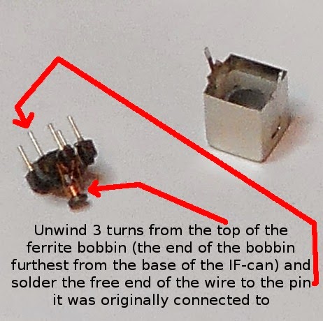
There appeared to be about eight turns for the winding between pin 1 and 2, which, conveniently, was the most accessible winding, located at the top of the ferrite bobbin.

Accordingly, to effect a reduction in inductance of about 30-40%, three turns had to be removed.


After three turns had been unwound, the wire was carefully scraped clean of enamel insulation and re-attached to pin 1 with the soldering iron, after which the shielding can was replaced. The windings were then checked for continuity with a multimeter.

After confirming continuity of the windings, the modified IF can was placed in the G3UUR colpitts circuit using the winding between pins 1 and 2 in place of the crystal.The oscillator could now be tuned from around 9.0MHz up to 11.0Mhz, which achieved the intended goal of 10MHz operation.

Monday 14 July 2014

Printer/Scanner film adapter EL wire (CCFL) inverter extraction

Some useful E-waste in the form of a Canon printer/scanner with a film adapter in the lid was pulled apart.

As well as some DC motors, shafts, screws, springs and plastic panels, an EL wire (CCFL) light source was found in the lid that served as a 35mm slide or 35mm film trans-illumination source.

The first step in awakening the light source was to establish the polarity of the two wires going to the CCFL inverter module.

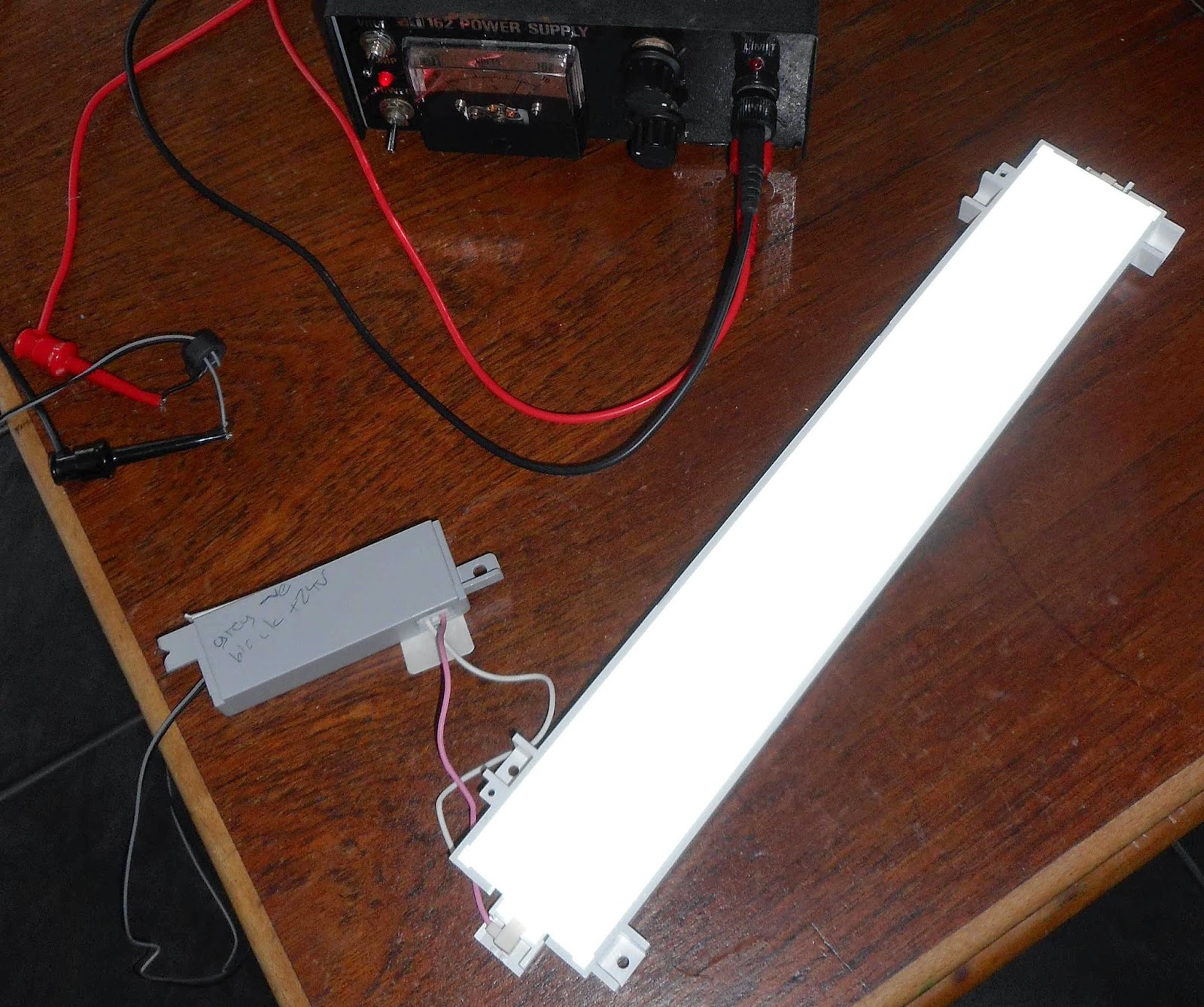
The two lower voltage wires which ran to the CCFL inverter from the printer's main PCB were grey and black, and the high tension wires going to the EL wire were pink and white.

The circuit board of the inverter had no markings to indicate the polarity of the lower voltage grey/black pair, but a transistor near the low voltage grey/black input jack had its emitter marked on the PCB, and this was common to the grey wire.
Further inspection of the PCB traces confirmed that a nearby electrolytic capacitor's negative lead was common to the emitter and the grey lead, making the grey lead GROUND, and the black lead POSITIVE.

A variable voltage DC supply was connected to the leads and the voltage slowly increased. Half the CCFL panel lit up somewhere in the order of 15V, and by 24V it was fully lit.

This was consistent with one of the DC voltage produced by the AC->DC SMPS module in the printer being 24V, with no 12V or 5V options.

At 24V DC, the inverter was drawing around 200mA. The plastic surround will be retained and a small lamp is planned in conjunction with a spare 24V wall wart / DC plug pack.

Maybe someone pulling something similar apart will find this useful and possibly avoid destroying their inverter if it has similar BLACK=positive wiring.


Wednesday 25 June 2014

A PCM290x based USB sound card for radio amateur and other uses

UPDATE:

design files are on github for the board, which will accommodate the PCM2902, PCM2904, PCM2906 versions (well, the PCM290x USB sound card IC family generally).

https://github.com/erichVK5/PCM290x-USB-audio-interface

I get the boards made by hackvana, who can be found on Freenode in #hackvana.

Open hardware for the win!

---------------------

The June 2014 edition of Amateur Radio magazine published a design for a USB sound card based on the PCM290x family of CODECs.

The depicted prototype used the PCM2904:


The board has optional connectors for the 3 switches supported by the CODEC, an SPDIF header for the codec models that support it, as well as space for 2 optional input and 2 optional output level adjustment potentiometers (Jumpered with 4 small wire links in the photo).

The board is 50mm x 50mm and has been designed for easy mounting in existing commercial rigs or homebrew rigs, or as a standalone unit. Input and output 3.5mm stereo sockets are supported to make connections simpler, as well as simple headers for those not using 3.5mm audio leads, and a Type B USB socket mounts directly to the board.

The option of an external regulated power supply for the ADC/DAC section of the CODEC is also supported.

Soldering was quick and easy, in fact three boards were done at once, using my hotplate liftoff jig technique.

A quick test after construction was successful with a G5RV equipped FT-817:


SDR homebrewers need to be aware of the one sample audio packet misalignment issue in some of the PCM290x revisions, and must either

1) choose unaffected revisions by studying the errata, or
2) empirically determine if the codec used does it, or
3) adjust their software to avoid phasing errors if using an affected codec

High quality hackvana made boards are now available at Aztronics

Here's the artwork, but homebrewers may struggle with the vias.


"Battery exhausted" on the Nikon Coolpix S3600 - a workaround - and Nikon firmware update hints for linux

The fairly new Nikon Coolpix S3600 had not been charged for a few weeks, and on trying to charge it with a USB cable, the charging light on the camera flashed rapidly  indicating an inability to charge, and then a "Battery exhausted" message appeared on the screen, and then the camera turned itself off completely.

This was a pretty revelatory disclosure from a device I was trying to charge.

It had a certain Rube Goldberg-esque-ness about it too.

The camera's manual told me it wouldn't charge below 5 degrees C. It was warmer than that, but I tried warming the battery in my hands and tried again - no luck.

I tried with the SD card in, out, back in again. No luck.

This seems to be a problem common to Li-ion batteries, namely, difficulty charging when a bit flat. The battery was an EN-EL19 3.7V 700mAh 2.6Wh battery.

I tried voltages ranging between 4.2V and 5.5V on the USB cable, but there was no change to the rapidly flashing light on the camera indicating inability to charge.

Some googling found the Nikon help page, which suggested a firmware upgrade to fix the charging problem that occurs with fairly flat batteries for multiple models, but the S3600 was not among the models with a firmware update available.

Furthermore, for the models listed, the instructions, for either OSX or Windows, both required me to turn on the camera and use the menu system to undertake the firmware upgrade... and also use the camera to format an SD card to deliver the new firmware.... Attentive readers will have noticed that the camera battery was flat.... or rather... "Battery exhausted"...

Further reading of the manual told me that the camera can charge slowly while attached to a computer. After plugging the camera into the linux netbook, however, it dutifully mounted, and the slow flash of the light on the camera told me it was now charging.

Well, this got around the unwillingness to charge problem.

I emailed Nikon about the problem. They got back to me within 24 hours and suggested I take it to an authorised repair centre.

"Kindly be advise that currently no known issue about the charging of the battery for the S3600. Kindly you may take the camera to the nearest Nikon service centre for further inspection. Details of the service centre are as per below:"
This seemed odd, because I found at least one reference to the same problem by another S3600 owner, a Mr S. McKay, on the web, and he'd been charged about the price of the camera in repairs not covered by warranty for what seemed like the same issue:

https://plus.google.com/110211862212172386392/posts/FYdHaGqjzAB

With a workaround now for the charging problem, I couldn't see the point of taking it anywhere. I will have to wait and see if they release a firmware update.

I was curious though about how I would be able to do an update using GNU/Linux. Having a look at some of the available firmware, I found it was available as either a self executing .exe archive, for example F-S6300-V11W.exe, or an OSX hfsplus compressed filesystem ".dmg" file, for example F-S6300-V11M.dmg, in the case of the S6300 model anyway.

... good to know that Nikon cater to both types of operating system...

So, for a worked exercise, and as a bit of a how to for others using GNU/Linux, I thought I'd extract firmware using ubuntu flavoured GNU/Linux for the S6300... that way, when an S3600 update is eventually released, I won't need to reinvent the wheel, and others might find it useful.

Nikon firmware update linux howto:

This guide uses the Nikon S6300 as an example.

Other Nikon camera firmware files may differ.

Firmware upgrade instructions for other cameras may also differ.

Be warned, using this guide with the wrong firmware could brick your camera, so use at your own risk.

Carefully compare these instructions with those provided by Nikon on their support website, to ensure you do not inadvertently brick your camera.

Repeat, use at your own risk!!!

First, download the OSX file F-S6300-V11M.dmg from the Nikon website into a local working directory, i.e.
~/Coolpix/
Then, you need to download the latest sourcecode for the dmg2img utility from
http://vu1tur.eu.org/tools/
which at the time of writing is dmg2img-1.6.5.tar.gz
gunzip dmg2img-1.6.5.tar.gz
tar xvf dmg2img-1.6.5.tar
cd  dmg2img-1.6.5
make

if you get "error: bzlib.h: No such file or directory"
sudo apt-get install libbz2-dev

if you get "error: openssl/sha.h: No such file or directory"
sudo apt-get install libssl-dev
then try to run make again

you can then run dmg2img from this directory to uncompress F-S6300-V11M.dmg

./dmg2img -i ../F-S6300-V11M.dmg -o ../F-S6300-V11M.img

You should see something like:
dmg2img v1.6.5 (c) vu1tur

../F-S6300-V11M.dmg --> ../F-S6300-V11M.img


decompressing:
opening partition 0 ...             100.00%  ok
opening partition 1 ...             100.00%  ok
opening partition 2 ...             100.00%  ok
opening partition 3 ...             100.00%  ok

Archive successfully decompressed as ../F-S6300-V11M.img

you now have an uncompressed hfsplus filsystem image called F-S6300-V11M.img in your  working directory. Go back to your working directory.
cd ..
I'll assume you don't have hfsplus filesystem support installed. You need to install ... you guessed it... hfsplus
sudo apt-get install hfsplus
sudo modprobe hfsplus
Now, you should be able to mount the image as a virtual device on a suitable mount point, in this case, I have chosen /mnt as a suiatble spot to mount it
sudo mount -o loop -t hfsplus ./F-S6300-V11M.img /mnt/
Then, if it has worked, you can
cd /mnt
ls -la
And you should be greeted with:
total 8204
drwxr-xr-x  1 root root       8 Apr  3  2013 .
drwxr-xr-x 23 root root    4096 May 31 00:26 ..
----------  1 root root 8388608 Apr  3  2013 .journal
----------  1 root root    4096 Apr  3  2013 .journal_info_block
drwxr-xr-x  1  501  501       3 Apr  3  2013 S6300Update
-rw-rw-rw-  1 root  501    3784 Apr  3  2013 .SymAVQSFile
d-wx-wx-wt  1  501  501       2 Apr  3  2013 .Trashes
You can then
cd S6300Update/
cd firmware
ls -la
and you will find
total 21636
drwxr-xr-x 1 501 501        3 Apr  3  2013 .
drwxr-xr-x 1 501 501        3 Apr  3  2013 ..
-rwxr--r-- 1 501 501 22151360 Mar 25  2013 firmware.bin
it is the "firmware" folder containing the "firmware.bin" file that needs to be copied onto the root directory of an SD card that has been freshly formatted in the camera.

I chose to copy the firmware folder to my working directory called "Coolpix" at this point
cd ..
cp -R firmware ~/Coolpix
cd ~/Coolpix
I then unmounted the virtual filesystem
sudo umount /mnt
So, you now have a local copy of the firmware.

your Camera should be charged by now. Press the menu button, go into the tools "Wrench/spanner" icon, and scroll down to Firmware. It should say "Version 1.0" if you have the battery charging issue.

Now, insert a spare SD card and format it in the camera. Having done this, turn the camera off.

Insert the SD card in the linux machine which should automount it
df
should show something like (for my spare 512MB SD card it shows this):
/dev/sdb1         495232        64    495168   1% /media/NO_NAME
now, copy the firmware file over to the card
cp -R firmware/ /media/NO_NAME/
Then check if it is there
ls /media/NO_NAME/
which should show:
DCIM  firmware  MISC  NIKON001.DSC
then look in the firmware folder:
ls /media/NO_NAME/firmware/
which should show something like:
-rw-r--r-- 22151360 Jun 25 00:09 firmware.bin
then unmount the card:
sudo umount /media/NO_NAME/
then put the card into the camera. Turn the camera on, press the menu button, go into the tools "Wrench/spanner" icon, and scroll down to Firmware. It should allow you to upgrade if you have the right firmware.