Homebrew, open source, repurposed, hacked, software defined, open hardware

Wednesday, 5 September 2012

Fixing a sunbeam food processor triac - or - using electronics to impress significant others

The wife wanted to make Tiramisu.

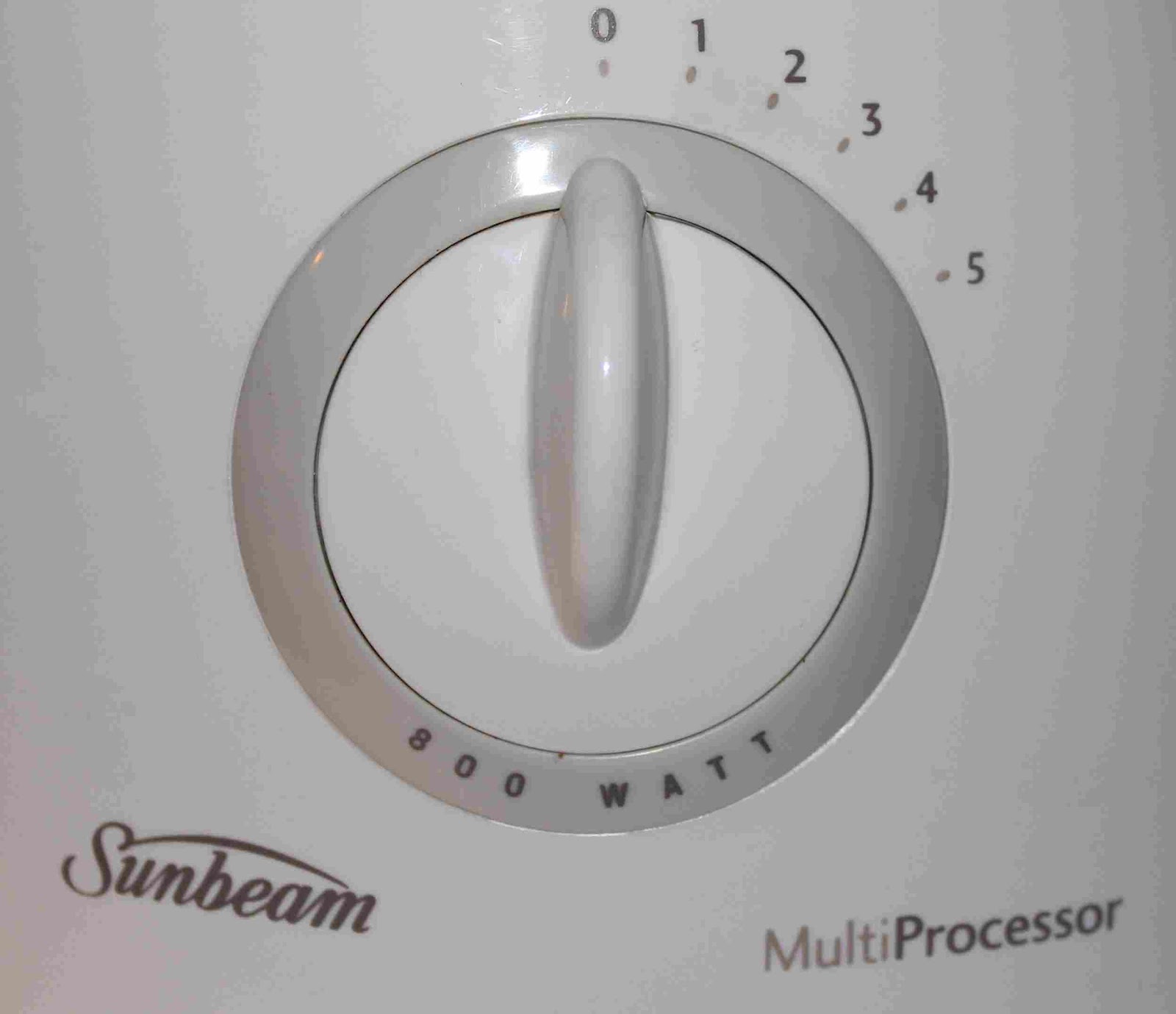
As soon as the food processor was plugged in, it remained on at full speed until unplugged.

No speed control!! No on or off!! Tiramisu to be made!! Horror!!

Luckily, improvisation with a grater allowed the chocolate to be grated for the Tiramisu, but the mystery of the somewhat manic food processor remained.

There was of course the bigger problem of under-engineered appliances going into landfill after trivial, easily fixed breakdowns.

Before taking it part, we already knew that the food processor motor worked.

This ruled out a blown fuse, an armature or brush problem, or a blown winding in the motor, or a cold solder joint going open circuit.

The failure of the on or off and speed control switch to work did however suggest a problem with the speed selection and control circuitry.

For the impatient, the fix involved replacement of the BT137 triac and associated DB3 Diac, purchased for just a few dollars from the local electronics store.

For those interested in the gory details, read on:

Cautionary note

Disassembly is shown in stages.

Please note that the food processor is double insulated.

This means that there is no earth wire going to the appliance.

This means that if you are well insulated, have removed the enclosure of the food processor, and have it plugged into a power point, and poke around with a screw driver, you will probably put yourself between active and neutral, act as a large carbon resistor, and go into ventricular fibrillation, and your heart will stop producing useful output.

As blood ceases to be pumped, and you are slipping into unconciousness and death, you may smell burning flesh as the residual earth leakage detector so thoughtfully installed in your meter box fails to trip as you have not provided it an earth return (earth wire) to carry any leakage current. Your only hope of survivial at this point is you trip the circuit breaker by drawing more than 10 amps, or loss of bladder control trips the earth leakage breaker, or someone nearby manages to unplug and resuscitate you without electrocuting themselves.

Alternatively, don't work on it while it is plugged in and open. Having cautioned you about working on live appliances, we can move on.....

Disassembly

The unmolested food processor:


First, the utensil drawer must be removed to expose two screws:


This allows the motor lid to be carefully popped off, to expose the safety interlock assembly and another screw:


Note the pivoted toggle which is pressed onto a plastic split pin. This toggle transmits the interlock motion arising from the insertion of the food processing bowl to the safety interlock microswitches. The toggle has to be gently pried off its split pin and carefully extracted otherwise the upper shroud can't come off:


Now remove the remaining screw:


Next, the drive shaft sleeve must be removed. Identify the flush tab on the drive spindle, pop it out, and slide off the plastic spindle:


Next, remove the speed selection switch by carefully unclipping and prying it free: 


Next, unscrew the four rubber feet and all of the phillips head screws on the base, including the recessed one in the middle, and lift off the upper portion of the enclosure to expose the internals.

The motor assembly can be seen here, with its armature and carbon brushes in plain sight at the top.


The other side of the motor enclosure has the safety interlock microswitches, actuated by the arm moved by the toggle you removed earlier:


The safety interlock microswitches seemed fine, and this was to be expected given that the motor ran at full bore when the unit had been plugged in.

The drive train can be seen here, when lifting up the assembly off the baseplate:


The base plate:


The remaining side of the motor enclosure has the speed control PCB, connected to the overlying "switchboard" containing the speed selection rotary switch and "pulse" micro switch. The uppermost rotary position is unconnected and acts as an off position, as it provides no AC to the Diac, which turns on the Triac:


Some side on views of the "switchboard" and PCB stack show some of the interconnecting wiring between the PCB and switches:


This view shows the active and neutral feeds coming to the PCB, and the active and neutral power feeds going off to the motor. Given that the motor was working at full speed, this meant that the problem was somewhere in-between the "power in" pair, and the "power out to the motor" pair, on the speed control PCB:


After undoing two screws holding the switchboard/speed control PCB stack to the motor housing, a further two screws can be removed to separate the switching board from the speed control PCB. Here's a view of the underside of the PCB and the wires going to the rotary speed selection switch and "pulse" microswitch. The yellow wire going to the rotary switch is the feed going to the rotary arm, and the four white wires go the resistive divider networks on the PCB for the different speeds. The other two yellow wires go to the "pulse" switch, which bypasses the resistive dividers:


 Here's a view of the underside of the PCB, with red circles around the PCB pads of interest for desoldering, namely, the DB3 Diac and BT137 Triac pads:


Here's a view of the topside of the circuit board, showing the BT137 Triac in a TO-220 package (black with three legs and integral heatsink) and the DB3 Diac which is the small blue cylinder marked Diac on the PCB:


Troubleshooting

On inspection of the circuit it became apparent that the active M+ wire to the motor was commoned to the active line going into the PCB. The triac's job was to complete the motor winding circuit by connecting the neutral feed to the M- wire going to the motor.

Nothing looked charred or burnt, so no smoke had escaped. The diodes tested just fine as did the resistors on the multimeter. I did not bother testing the capacitors at this stage as their failure was not considered likely.

If the Triac had suffered an insult from a power spike, perhaps from some inductive load nearby on the same power circuit, or from the motor itself in the food processor, it may have failed in a short circuit or easily triggered fashion.

Testing resistance across the T1 and T2 terminals of the BT137 triac did not identify a short circuit, and was open circuit (i.e. infinite resistance). Gate to T1 measured about 20 ohms, and on diode test mode about 20mV. Gate to T2 was open circuit, as it should have been.

The Diac also was not shorted, and tested open circuit on the ohm meter.

Despite the essentially normal findings on multimeter testing of the Diac and Triac, subtle failure could not be ruled out in which a power spike had caused a very localised failure within the triac which might only manifest as having a very low trigger threshold, allowing it to turn itself on straight away, rather than be subject to control of turn on threshold via current into its gate from the diac and resistive divider based control circuit.

The BT137 Triac and DB3 Diac were replaced, the unit reassembled, and the motor was found to once again be subject to the control of the on off and speed selection dial. Success.

Ideally, a more robust Triac should have been used in the design as this fault appears to be quite common, judging by Google.

Some Triac and Diac Theory

Triacs and Diacs may seem a bit exotic and mysterious to those new to electronics.

Simply put, the Triac is a solid state switch that can conduct AC, and needs current on the gate to trigger conduction. Apart from the AC aspect, it's behaviour is analogous to that of a simple bipolar transistor.

Where it gets interesting is how to control power going to a load with a Triac, such as a dimmable bulb, electric element, or a universal motor.

With a sinusoidal waveform, one can decide where along this waveform the Triac is to be turned on. This can be thought of as the trigger voltage, or the phase angle along the sinusoidal AC waveform.

This allows a variable amount of power to be supplied, and in this case motor speed, depending on where along the AC waveform the Triac is turned on.

The Diac is really just a voltage triggered switch. Above a certain voltage it turns on, allowing current to flow into the Gate of the Triac, to which it is connected.


In the food processor's circuit, speed control is achieved by a set of resistive dividers selected by the rotary switch, applying a voltage to the Diac.

These determine the threshold, and therefore the point along the AC waveform, at which the Diac switches on, thereby allowing current into the Triac, turning it and by extension the motor, on.

The pulse switch bypasses the rotary switch divider network and lets the motor go full bore.

Triacs commonly fail due to voltage spikes from reactive loads, and are a good place to start in misbehaving small appliances. The Diac was easy to replace and replacing it along with the Triac seemed easier than disassembling again to replace the Diac in the event that Triac replacement did not fix the problem.

If you want to learn more, Google Triac and Diac. I found a very good Thyristor Seminar presentation pdf by NXP that can be found by googling which discusses the history, types and usage of Triacs.

As well as keeping otherwise useful appliances out of landfill, you can learn a lot by troubleshooting and fixing appliances that don't work.

Anyone wishing to use the repair pictures is free to do so with attribution if it helps people fix their appliance.

Sunday, 4 December 2011

Client - Server model for software defined radios

having run some cabling from the bedroom to the study for the HPSDR
(USB extension lead primarily, plus a Cat6, Cat5, power, data and sundry audio for future mischief)


I could then run the HPSDR in the study


from the netbook in the bedroom. The netbook is running the ghpsdr3 software for the HPSDR, and in particular, the dspserver and hpsdr-server software which can allow clients on the network to access the HPSDR remotely


The white USB lead goes to the USB extension lead which goes to HPSDR in the study. The blue lead goes to the ADSL/router in the comms box...
And then the PC (ghpsdr3 software is installed too) hooked up to the TV is able to access the server application on the netbook, and is running QtRadio, the "remote head" part of the ghpsdr3 suite of software, which could also run on the netbook if I wanted to. End result, the TV in the lounge is now a remote head for the HPSDR!


The TV is tuned into a broadcast band AM station.

One can also run John Melton's (G0ORX) android remote HPSDR app, and here's the android tablet doing this over wifi:


Monday, 27 June 2011

Thoughts on tuned loop variable capacitors

While reading Jim VK5TR's article in July's Amateur Radio Magazine, Jim bemoaned the very narrow useful tuning range of butterfly variable capacitors, with fractions of a degree of rotation greatly altering loop tuning, necessitating the parallel addition of a fixed capacitor to the variable capacitor.

It occurred to me one could use cam or nautilus shaped plates in the variable cap on the loop.

Imagine, if you will, a capacitor with two plates which are circular. Rotating the plates axially 180 degrees relative to one another does not change the capacitance.

Now, add some lobes, like a cam in an engine, or like a nautilus profile in and old
school temperature controller or on nautilus  gym equipment.

Rotation of the cams from 0 through 180 degrees will yield the same capacitance
as the two circles when the cams  are at minimum engagement, and when the
lobes are at maximum overlap, the capacitance will be (the capacitance of the two circles at minimum engagement) + (the capacitance of the the two overlapping lobes).

Ideally, the cam profile should be calculated to allow a linear increase in frequency across the desired portion of the band through which the loop is to tune as the capacitor is rotated from 0 to 180 degrees . If you are really keen on a particular part of the band, the cam could be modified to "stretch" this part of the band, to allow finer tuning.

See attached picture. I have only shown a simple two plate cap, but obviously for
higher Q you would implement it with a rotor betwixt two stators, etc....


Excuse the graphics, the GIMP is not ideal for this sort of thing.

Something for the must try this sometime list.

Custom RF and AV wallplates

Commercially available AV wallplates don't always blend in with standard wallplates, and sometimes you simply can't get off the shelf wallplates with some types of RF connectors.

This is how I use blank wallplates which match my existing wallplates to make custom AV, radio and whatever wallplates.

First of all, decide where to put the connectors. This will depend on connector size, wallplate size, wallplate curvature, ease of connector use if closely spaced, and loss of strength if you swiss cheese the plate too much, and of course, aesthetics.

In this case, two N connectors will be mounted, with their centres spaced 13 mm from the centreline. A set of calipers is used to score the plastic. The wallplate has centrelines already moulded in.


Having done this, carefully drill pilot holes centred on the marks.

Next, a step drill is used to make a hole the right size for the connector body. Step drills are indispensible for this sort of thing.
Next, accurately mark the wallplate where the mounting screw holes have to be drilled.

Then carefully drill at the marked locations

Then mount your connectors

Then prepare your cabling for the connectors and mount the wallplate.


Then use it! This wall plate brings the quad band antenna to the FM8900.
N connectors are better than BNC or SO-239 connectors for VHF, UHF and microwave bands, as they are less lossy on account of better impedance matching as the RF makes its way through the connector, and can handle fairly high power levels.

Thursday, 9 June 2011

Fixing the OzRoll roller shutter controllers once and for all

To summarise, OzRoll (TM) make a pretty solid and nice roller shutter, which we wanted in our bushfire prone and cold location.

The roller shutter controller which comes with the roller shutters uses an ATMega to monitor for key presses, raise and lower the roller shutter, decide when the roller shutter has finished moving, and, decide when and for how long the NiMH battery pack needs charging.


Unfortunately, the NiMH battery packs seem to die fairly easily, and we had four or so dead on arrival, as the roller shutters were installed some time before the house was ready to move into. Googling revealed multiple sources of replacement packs for about AUD$80. Ouch.


An early enquiry made to the installer revealed that OzRoll, the local manufacturer, had said that after 6 months or so, the batteries were out of warranty, so tough luck.


Disassembly of some of the roller shutters was undertaken to exclude mechanical causes for excessive motor current requirements.


The front panel was removed by drilling out four rivets. No dead rodents or invertebrates of note, even after lowering!


The roller shutter axle was easily dismounted from the motor and opposite spindle.


The physical build was very good. I couldn't fault the engineering. The motor was nice and solid looking, and the power cable inlet appeared to be fairly well sealed.

Continuous power to the nominally 12V DC motor was met with continuous rotation.

Testing found that the instantaneous turn on current when initiating movement - with the roller shutter disconnected from the motor! - was as much as 4 amps. So, even a partly cactus 1500mAH battery pack was going to struggle.

The roller shutter motor, it turns out, has no start or stop switches, and the controller's ATMega was smart enough to be able rely on a sudden increase in current from the power supply to determine if the roller shutter has finished moving.


I suspect the flashing red LED (D8) on the roller shutter controllers saying they needed charging kicked in at some point and gradually drained the batteries in the roller shutter controllers until they were dead.

There is a position on the circuit board for a small on off switch has been bridged with a very puny wire link in all the controllers - who knows, this simple switch may have saved four or five NiMH battery packs from dying, and who knows how many others in other customers' roller shutters that are now in land fill.

I made a subsequent call to the manufacturer, leaving a message asking about replacement battery packs, but was never called back.

Unfortunately, the charging algorithm in the controller seems a bit broken, and allows ongoing charging with about 160mA for a predefined period. It does not seem to turn off when a certain voltage is reached in the battery pack, or care about the battery pack temperature. This would probably explain why the battery packs get so darned hot with charging. I would have thought with such a capable microcontroller, they could have done a bit better with the charging algorithm

I was reluctant to spend another AUD $400 to get battery packs which would eventually die in service as a result of slightly brain dead charging and excessive current demands.

Anyway, a few minutes with a soldering iron, some cable, a solder lug and a DC barrel connector and you'll be able to run the the controller off an external SLA battery. If you cut the circuit board track going to the LED (D8) which flashes when the controller wants to charge battery, you won't be annoyed by the ATMega's complaining about its inability to initiate a charging routine.

I was surprised by how puny the wire link was where the switch was supposed to go - it had to handle up to 4 amps at times. Most of the time the current required was between 1 and 1.5 Amps, well within the rating of a 2.5mm DC barrel connector I intended to standardise on.

First of all, after disassembling with a Torx screwdriver, and removing the battery pack, the original charging socket is removed to make way for the new power lead, and the wire link is removed form the empty switch position to allow make a beefier terminal to be put in for the positive of the new power lead.
After desoldering these, a bigger wire link is put in where the small wire link was, and the original charger plug opening is widened enough for the new power cable.

Then, cut the track to D8, the red LED that flashes whenever power is disconnected from the ATMega, and whenever the ATMega decides a charging session is in order. This is superfluous when an external power supply is used, and is an unnecessary annoyance. 


Having cut the track to D8, you can then prepare a negative terminal for the power cable. The positive terminal using a bigger wire link was a no-brainer, but there was no big fat nice place to solder the negative lead. Luckily, the back of the board is a ground plane, and a mounting screw in the middle of it was perfect for holding a negative terminal to the ground plane. Lacking a suitable tab, a second hand 13mm = 1/2inch copper pipe clamp was soft annealed in the fireplace, hammered flat, and trimmed to suit a patch of ground plane which had the solder mask scraped away.

After this, the power lead can be soldered to the +ve and -ve terminals.

And then put it together.


The unit can then have a DC barrel connector attached, paying careful attention that you make the positive lead (white stripe in the above picture) go to the centre of the DC barrel connector, which is the usual convention.


I will have the DC barrel connectors plug into a blank wall plate to the left, with DC barrel sockets. These barrel sockets will be wired to a compact 12V 3.3Ah SLA battery (only AUD$20 from Altronics!) which will be located further down the wall, in the wall cavity, with a standard wall plate covering the battery enclosure.


It is very important to have an inline fuseholder with a fuse, close to the battery, as shown above, to avoid exploding batteries and/or fused wires in the event of  accidental shorts. Lead acid batteries can explode too, if hydrogen leaks and finds a spark, but hey, other battery chemistries can explode too.

With the battery being terminated in a DC barrel connector on the wall plate, it can be charged with an SLA fixed voltage and current limited charger plugged in on an occasional basis, or, additional wiring can be run to the same wall plate to bring a charging circuit to the battery from a central location, which can be turned on as required, or fat DC cabling can be run to the controllers from a central location.

As a bonus, there's 12 volts on tap in the wall whenever you need it (within reason given the 3.3Ah capacity) for a radio transceiver perhaps...

As mentioned above, in a bushfire prone area, reliable roller shutters are important and mains power cannot be relied on in emergencies. Having a dedicated battery for each controller was an important consideration for us, and the mod described above even allows a separate power supply to be used with the controllers in case of emergency.

Cable, solder tag, and battery, about AUD$25. Even after adding a wallplate or two, some cable and a fuse and fuseholder, it sure beats a soon to be dead AUD$80 battery for each controller.

I'm sure the engineers were capable of making a more robust controller, but I can't help wondering if they had to contend with marketing who wanted a nice compact sleek unit, and went with 12x1.2Vx1500mAh AA NiMHs as a result.

I hope this helps similarly afflicted consumers out there, but it's not my fault if you void your warranty, kill your controller or hook up a high current power supply the wrong way around and melt something or burn the house down.