As soon as the food processor was plugged in, it remained on at full speed until unplugged.
No speed control!! No on or off!! Tiramisu to be made!! Horror!!
Luckily, improvisation with a grater allowed the chocolate to be grated for the Tiramisu, but the mystery of the somewhat manic food processor remained.
There was of course the bigger problem of under-engineered appliances going into landfill after trivial, easily fixed breakdowns.
Before taking it part, we already knew that the food processor motor worked.
This ruled out a blown fuse, an armature or brush problem, or a blown winding in the motor, or a cold solder joint going open circuit.
The failure of the on or off and speed control switch to work did however suggest a problem with the speed selection and control circuitry.
For the impatient, the fix involved replacement of the BT137 triac and associated DB3 Diac, purchased for just a few dollars from the local electronics store.
For those interested in the gory details, read on:
Cautionary note
Disassembly is shown in stages.
Please note that the food processor is double insulated.
This means that there is no earth wire going to the appliance.
This means that if you are well insulated, have removed the enclosure of the food processor, and have it plugged into a power point, and poke around with a screw driver, you will probably put yourself between active and neutral, act as a large carbon resistor, and go into ventricular fibrillation, and your heart will stop producing useful output.
As blood ceases to be pumped, and you are slipping into unconciousness and death, you may smell burning flesh as the residual earth leakage detector so thoughtfully installed in your meter box fails to trip as you have not provided it an earth return (earth wire) to carry any leakage current. Your only hope of survivial at this point is you trip the circuit breaker by drawing more than 10 amps, or loss of bladder control trips the earth leakage breaker, or someone nearby manages to unplug and resuscitate you without electrocuting themselves.
Alternatively, don't work on it while it is plugged in and open. Having cautioned you about working on live appliances, we can move on.....
Disassembly
The unmolested food processor:
First, the utensil drawer must be removed to expose two screws:
This allows the motor lid to be carefully popped off, to expose the safety interlock assembly and another screw:
Note the pivoted toggle which is pressed onto a plastic split pin. This toggle transmits the interlock motion arising from the insertion of the food processing bowl to the safety interlock microswitches. The toggle has to be gently pried off its split pin and carefully extracted otherwise the upper shroud can't come off:
Now remove the remaining screw:
Next, the drive shaft sleeve must be removed. Identify the flush tab on the drive spindle, pop it out, and slide off the plastic spindle:
Next, remove the speed selection switch by carefully unclipping and prying it free:
Next, unscrew the four rubber feet and all of the phillips head screws on the base, including the recessed one in the middle, and lift off the upper portion of the enclosure to expose the internals.
The motor assembly can be seen here, with its armature and carbon brushes in plain sight at the top.
The other side of the motor enclosure has the safety interlock microswitches, actuated by the arm moved by the toggle you removed earlier:
The safety interlock microswitches seemed fine, and this was to be expected given that the motor ran at full bore when the unit had been plugged in.
The drive train can be seen here, when lifting up the assembly off the baseplate:
The base plate:
The remaining side of the motor enclosure has the speed control PCB, connected to the overlying "switchboard" containing the speed selection rotary switch and "pulse" micro switch. The uppermost rotary position is unconnected and acts as an off position, as it provides no AC to the Diac, which turns on the Triac:
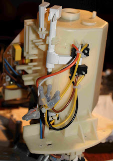
Some side on views of the "switchboard" and PCB stack show some of the interconnecting wiring between the PCB and switches:
This view shows the active and neutral feeds coming to the PCB, and the active and neutral power feeds going off to the motor. Given that the motor was working at full speed, this meant that the problem was somewhere in-between the "power in" pair, and the "power out to the motor" pair, on the speed control PCB:
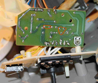
After undoing two screws holding the switchboard/speed control PCB stack to the motor housing, a further two screws can be removed to separate the switching board from the speed control PCB. Here's a view of the underside of the PCB and the wires going to the rotary speed selection switch and "pulse" microswitch. The yellow wire going to the rotary switch is the feed going to the rotary arm, and the four white wires go the resistive divider networks on the PCB for the different speeds. The other two yellow wires go to the "pulse" switch, which bypasses the resistive dividers:
Here's a view of the underside of the PCB, with red circles around the PCB pads of interest for desoldering, namely, the DB3 Diac and BT137 Triac pads:
Here's a view of the topside of the circuit board, showing the BT137 Triac in a TO-220 package (black with three legs and integral heatsink) and the DB3 Diac which is the small blue cylinder marked Diac on the PCB:
Troubleshooting
On inspection of the circuit it became apparent that the active M+ wire to the motor was commoned to the active line going into the PCB. The triac's job was to complete the motor winding circuit by connecting the neutral feed to the M- wire going to the motor.
Nothing looked charred or burnt, so no smoke had escaped. The diodes tested just fine as did the resistors on the multimeter. I did not bother testing the capacitors at this stage as their failure was not considered likely.
If the Triac had suffered an insult from a power spike, perhaps from some inductive load nearby on the same power circuit, or from the motor itself in the food processor, it may have failed in a short circuit or easily triggered fashion.
Testing resistance across the T1 and T2 terminals of the BT137 triac did not identify a short circuit, and was open circuit (i.e. infinite resistance). Gate to T1 measured about 20 ohms, and on diode test mode about 20mV. Gate to T2 was open circuit, as it should have been.
The Diac also was not shorted, and tested open circuit on the ohm meter.
Despite the essentially normal findings on multimeter testing of the Diac and Triac, subtle failure could not be ruled out in which a power spike had caused a very localised failure within the triac which might only manifest as having a very low trigger threshold, allowing it to turn itself on straight away, rather than be subject to control of turn on threshold via current into its gate from the diac and resistive divider based control circuit.
The BT137 Triac and DB3 Diac were replaced, the unit reassembled, and the motor was found to once again be subject to the control of the on off and speed selection dial. Success.
Ideally, a more robust Triac should have been used in the design as this fault appears to be quite common, judging by Google.
Some Triac and Diac Theory
Triacs and Diacs may seem a bit exotic and mysterious to those new to electronics.
Simply put, the Triac is a solid state switch that can conduct AC, and needs current on the gate to trigger conduction. Apart from the AC aspect, it's behaviour is analogous to that of a simple bipolar transistor.
Where it gets interesting is how to control power going to a load with a Triac, such as a dimmable bulb, electric element, or a universal motor.
With a sinusoidal waveform, one can decide where along this waveform the Triac is to be turned on. This can be thought of as the trigger voltage, or the phase angle along the sinusoidal AC waveform.
This allows a variable amount of power to be supplied, and in this case motor speed, depending on where along the AC waveform the Triac is turned on.
The Diac is really just a voltage triggered switch. Above a certain voltage it turns on, allowing current to flow into the Gate of the Triac, to which it is connected.
In the food processor's circuit, speed control is achieved by a set of resistive dividers selected by the rotary switch, applying a voltage to the Diac.
These determine the threshold, and therefore the point along the AC waveform, at which the Diac switches on, thereby allowing current into the Triac, turning it and by extension the motor, on.
The pulse switch bypasses the rotary switch divider network and lets the motor go full bore.
Triacs commonly fail due to voltage spikes from reactive loads, and are a good place to start in misbehaving small appliances. The Diac was easy to replace and replacing it along with the Triac seemed easier than disassembling again to replace the Diac in the event that Triac replacement did not fix the problem.
If you want to learn more, Google Triac and Diac. I found a very good Thyristor Seminar presentation pdf by NXP that can be found by googling which discusses the history, types and usage of Triacs.
As well as keeping otherwise useful appliances out of landfill, you can learn a lot by troubleshooting and fixing appliances that don't work.
Anyone wishing to use the repair pictures is free to do so with attribution if it helps people fix their appliance.


