Homebrew, open source, repurposed, hacked, software defined, open hardware

Wednesday 19 July 2017

PolyHatch command for cross hatching polygons in pcb-rnd

During development of the Protel Autotrax/Easytrax layout format import/export plugin, a separate polygon helper plugin was also developed to facilitate conversion of complex polygons into cross hatched versions.

This allowed export of complex Polygons to Protel  Autotrax/Easytrax format, which only supports lines and rectangular solid fills.

Because the cross hatching routine is just another plugin, the command can be applied to any polygon in a layout, if the need arises.

The command is invoked with the usual colon typed at the keyboard, followed by the command

i.e. ":PolyHatch(interactive)"


To use the command, you need to have a polygon or polygons selected. Here, we are using a layout with open hardware logos to demonstrate:


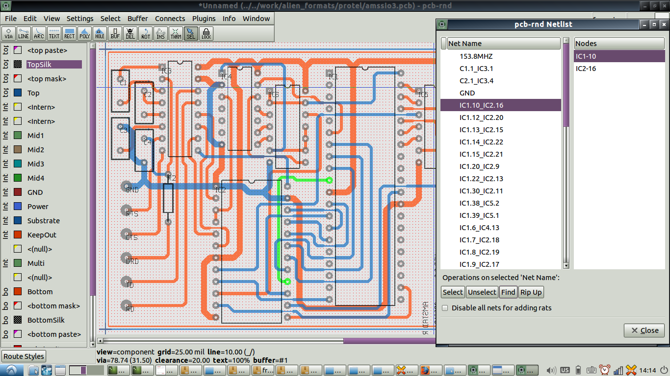
First, you need to select a polygon to crosshatch. Here, we select a logo on the top silkscreen layer:


After issuing the command

:PolyHatch(interactive)

the interactive dialog window appears:


The dialog allows the hatching style, clearances and spacing to be specified:


After hitting OK, the polygon will be crosshatched using the currently selected layer (in this example "Top component" copper), and the new cross hatched version of the polygon will appear in addition to the original polygon:


The still selected, original polygon can be deleted, leaving the cross hatched version. Note that the cross hatching has appeared on the currently selected top component copper layer, not the top silk layer of the original polygon:


Multiple polygons can be selected for simultaneous conversion, i.e:


Note also that we have switched the active layer to the Ground plane layer. We now invoke the :PolyHatch(interactive) command again


After deleting the selected original polygons which are not needed, we now find the cross hatched versions on the ground plane:


Free fills or copper pours are a more typical target for the PolyHatch cross hatching function.

Here is a top copper polygon drawn over a DIP footprint with some additional tracks with associated clearances:


The polygon is selected, and the :PolyHatch(interactive) command invoked:


After deleting the original selected polygon, we are left with a cross hatched ground plane:


It is worth noting that the "Rubberband" tracks placed with rubber band mode contain arcs, and that these arcs have had their clearances preserved, i.e. pcb-rnd, like gEDA PCB, supports DRC for arcs on copper layer.

In addition to facilitating export to legacy formats such as Protel Autotrax/Easytrax, the PolyHatch plugin is likely to be useful for creating capacitative sensors on PCB layouts, as well as facilitating more creative designs, i.e.


For those using Kicad, and lacking an easy means of crosshatching a polygon for use as a capacitative sensor or to modify transmission line impedance, pcb-rnd can load and export Kicad format layouts, greatly simplifying this task.

The above tennis racquets can be saved in Kicad s-expression format quite easily. The only caveat is that Kicad does not support arcs on copper, which were used for the racquet frames. After shifting the racquets to the silk layer (to get around Kicad's limitations with arcs) the layout can be exported with "File:Save As"


and then saved as a Kicad s-expression format layout


after which, the layout can be viewed in Kicad's pcbnew layout editor, complete with cross hatched polygons:


Friday 7 July 2017

pcb-rnd support for Protel Autotrax / Easytrax layout file import and export

An additional import/export module has been developed in the FOSS PCB layout tool pcb-rnd to allow layouts in Protel Autotrax and Protel Easytrax formats to be imported and exported.

Protel Autotrax and Protel Easytrax were industry standard DOS based PCB design tools in the early 1990s. Protel Easytrax was a cut down version of Protel Autotrax. The more capable Protel Autotrax required a dongle to operate.

Altium recently released Protel Autotrax as freeware, and it still has something of a following among those familiar with it who are happy to continue using it in a DOS emulator. Arguably, those with low end hardware in educational or hackerspace contexts may still find Protel Autotrax quite adequate for PCB design stations, particularly now that subsequent conversion to multiple formats is possible with pcb-rnd.

The import/export feature will primarily be of use to those seeking to:
  • modify previously distributed Protel Autotrax and Easytrax designs in something other than the original Protel Autotrax software
  • use legacy Protel Autotrax and Easytrax designs sourced from others to generate gerbers for fabrication
  • export footprints and designs for existing Protel Autotrax users 
  • convert Protel Autotrax and Easytrax designs into any of the other formats supported by pcb-rnd, such as postscript, png, svg, gcode, XYRS, kicad legacy layouts, kicad s-expression layouts, etc...
  • convert old footprints in Protel Autotrax and Easytrax designs for use in more modern tools.
Netlists are also imported along with Protel Autotrax and Easytrax design  geometry.

Because Protel Autotrax and Easytrax only support rectangular polygonal copper pours, the exporter will export any complex, non-rectangular polygons in a design as an outline of the islands and holes, and cross hatch the interior.


Simple rectangular polygonal pours are however exported as standard Protel Autotrax/Easytrax rectangular "Free Fill" rectangles.

For lines, 90 degree arc segments, pads and pins, however, exporting to Protel Autotrax format will be essentially lossless, within the limitations of the 1 mil resolution of the Protel Autotrax/Easytrax format, and 90 degree quadrant arc support in the Protel Autotrax/Easytrax format

Protel Moiro Targets and Cross Hair targets are not supported on import.

Also, pins and vias with connection/clearance flags for the GND and POWER copper layers are not acted on. This will not be an issue for any designs which do not have dedicated GND and/or POWER copper layers.

"Multi" and "board" layer elements are combined with the top silk layer during import into pcb-rnd, as they are not explicitly supported as layer types in pcb-rnd.

"Keepout", which delineates the board outline and cutouts, is mapped to the outline layer in pcb-rnd.

For those keen to implement an importer for some other format, the io_autotrax code would serve as a good template for those keen to give rolling their own a go. Alternatively, if provided with sufficient, suitable examples and summary information for a given format, we can look at the feasibility of implementing the importer.

Here's a nixie clock layout from lupinesystems


Here's a PICAXE40 radio controller board loaded into pcb-rnd: 


Here's a QRP SSB 80m transceiver design loaded into pcb-rnd


This screenshot shows the netlists loaded along with a single board Z80 computer layout:


this screenshot of the SSB transceiver layout loaded into pcb-rnd shows how Autotrax users create pours without the use of polygons


Here's a VK3BHR LC-meter design developed in pcb-rnd:


and here it is after a round trip to and from Protel Autotrax format, showing how complex polygonal copper pours are replaced by outlines of the polygonal islands and holes by the exporter, which are then filled with cross hatching:


Here's another example with cross hatching applied to polygons on export:


after saving as Protel  Autotrax, and then loading it back into pcb-rnd, the crosshatching used in place of the complex polygonal copper pour can be seen:


And yeah, here is a q-meter layout by the inimitable VK5JST/VK5TR


And finally, a frequency meter by Dave Jones, yep.... that Dave Jones