I liked the idea of a USB bus sniffer that could be interposed between the computer and the peripheral, as described in a recent silicon chip magazine. I thought it might come in useful for anticipated Arduino hacking in the near future.
I thought about what was needed to make a board to fit the USB A and B connectors, and then having to source the connectors from dead hardware like a discarded printer, and then find a suitable enclosure which would allow USB port accessibility. Hmmm. I then saw a USB power injector kit on sale at Altronics for AUD$12
http://www.siliconchip.com.au/cms/A_102685/article.html
http://www.altronics.com.au/index.asp?area=item&id=K2910
well, this was 90% of the work already done, and all that was needed were some banana posts for the D+, D-, 5V and Ground terminals, and as a bonus, it could inject power for whatever peripheral I was working on.
An extra switch seemed worthwhile to switch between the PC 5V USB supply and external plugpack 5V power injection.
Here's the modified circuit, with due deference to Silicon Chip's original circuit.
How the board comes:
How the board comes bottom side view. Not a lot of space for four connectors, but just enough, it turns out:
Holes were drilled where space was kind of available for the banana post stems for the D+, D-, 5V and Ground connections, and an extra hole to allow a 10uF tantalum to sit out of the way of the Ground banana post:
The box lid was drilled using the circuit board as a template to match the banana post locations, and for the DPDT miniature switch. When finally assembled, the red banana post does not have the nut attached, as it would likely short out the LM7805 heat sink:
The lid was then put together followed by the board trackwork being cut to allow the external 5V supply to be switched in and out, and to allow the banana posts to be connected, and to keep components which would get in the way to be re-routed:
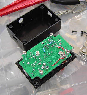
The board was then populated with components on the top side, and the DPDT switch was then wired to allow pass through for the USB B -> A power, or via the power injection circuit. One of the tantalum cap legs had to go into one of the new holes drilled to keep it out of the way of the Ground banana post, and two resistors had to go under the board to keep them out of the way of the D+ and D- banana posts:
The underside of the board was finished off, and the 5V banana post got its own PCB island just north of the LM7805 heat sink for the wiring from the switch, which then went on to the Type A USB connector. Hint for young players - the stems of the banana posts wet very easily with solder if you spin some 180 grit sandpaper or similar around them to get through the oxide layer on the electroplating before you solder to them. Scraping with something sharp will also do the trick:
Finally assembled:
The switch allows selection of the 5V source, and the red and black banana terminals gave 5.15V from the netbook and 5.01V from the internal 7805 regulator when running off an external plugpack.
Green and white are D+ and D-.
The original article describing the bus sniffer showed a 1 ohm resistor that could be placed in series or shorted with a jumper to allow measurement of the current being drawn by the device. This seemed a little superfluous if a power supply with a current readout and/or current limiting is used for external powering of the USB device with this unit, but a jumpered resistor could be shoehorned into the box if one were really keen.
So, in conclusion, if you want to build a USB bus sniffer, a power injector my be an easy way to do it, with the added bonus of not frying your USB host if things go a bit haywire with power requirements.
I suppose I should get my hands on an arduino now.


It is a very informative and useful post thanks it is good material to read this post increases my knowledge. Roller Shutters Canberra
ReplyDelete